Torque (Definition): Measuring Rotational Force Effectiveness
Torque (Definition) quantifies how effectively a force causes rotational motion about a chosen point or axis: . Use it when you need the rotational effect of a force about a chosen point or axis, not just the force’s magnitude.
Torque is the rotational analog of force. While force causes linear acceleration, net torque causes angular acceleration. The magnitude of torque depends not only on the force’s magnitude but also on where and how it’s applied: a force applied farther from the pivot point creates more torque, and a force applied perpendicular to the lever arm is maximally effective. Understanding torque is essential for analyzing everything from opening doors to balancing seesaws to designing engines.
On this page: The Principle · Conditions · Misconceptions · EE Questions · Retrieval Practice · Worked Example · Solve a Problem · FAQ
The Principle
Statement
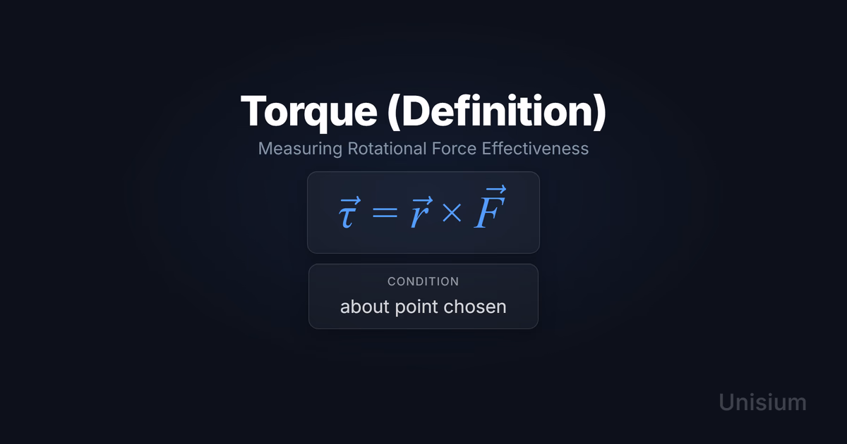
The torque produced by a force about a chosen point (or axis) is defined as the cross product of the position vector (from the reference point to the point of force application) and the force vector . The magnitude of torque measures how effectively the force causes rotation, and the direction of the torque vector indicates the axis and sense of rotation. Torque about an axis is the component of along that axis.
Mathematical Form
Where:
- = torque vector (N·m, newton-meters)
- = position vector from pivot point to point of force application (m, meters)
- = force vector (N, newtons)
- = vector cross product operator
Alternative Forms
In different contexts, this appears as:
- Magnitude (planar problems): where is the angle between and
- Perpendicular distance form: where is the perpendicular distance from the rotation axis to the line of action of the force (lever arm)
Conditions of Applicability
Condition: about point chosen This means torque is defined with respect to a specific reference point or axis that you must choose. Different pivot points yield different torques for the same force. The choice of reference point is arbitrary but must be stated explicitly—common choices include the axis of rotation, a support point, or the center of mass.
Practical modeling notes
- Reference point selection: For objects with a fixed axis of rotation (hinges, axles), choose the axis as your reference point. For free objects, any point works mathematically, but the center of mass or a contact point often simplifies the problem.
- Sign conventions: In planar problems, torques are often treated as scalars with signs: counterclockwise torques are typically positive, clockwise negative (or vice versa, as long as you’re consistent).
- Zero torque cases: A force produces zero torque if (1) it passes through the reference point (), or (2) it’s parallel or antiparallel to ().
When It Gets Tricky
- Distributed forces or deformable bodies: The definition assumes a point force on a rigid body. For continuous force distributions or elastic bodies, you need to integrate over the distribution or account for internal stresses.
- Non-inertial frames: The torque definition still works, but fictitious forces (centrifugal, Coriolis) appear in the dynamics and contribute their own torques. Work in an inertial frame when possible, or explicitly include fictitious contributions.
Want the complete framework behind this guide? Read Masterful Learning.
Common Misconceptions
Misconception 1: Torque depends only on the force magnitude
The truth: Torque depends on both the force magnitude and where it’s applied. The same force produces different torques depending on its distance from the rotation axis and its direction relative to the position vector.
Why this matters: A small force applied far from the pivot (long wrench) can produce more torque than a large force applied close to the pivot (short wrench). This is why door handles are placed far from hinges and why wrenches have long handles.
Misconception 2: The vector can be any vector
The truth: The position vector must run from the chosen reference point (often the axis of rotation) to the point where the force is applied. Using the wrong reference point or measuring from the wrong location yields incorrect torque values.
Why this matters: In problems with multiple forces, each force has its own vector measured from the same reference point. Mixing reference points or measuring from force application points to each other produces nonsense results.
Misconception 3: Torque and force are the same thing
The truth: Torque is not a force—it’s a rotational effect produced by a force. Torque has units of N·m (not N), measures effectiveness at causing rotation (not translation), and is a vector perpendicular to the plane of rotation (not along the force direction).
Why this matters: You cannot “add” a torque to a force or substitute torque into . Forces cause linear acceleration; torques cause angular acceleration via .
Elaborative Encoding
Use these questions to build deep understanding. (See Elaborative Encoding for the full method.)
Within the Principle
- Why does the cross product structure capture both the magnitude of torque (through ) and the axis of rotation (through the direction of )?
- What do the units N·m tell you about the physical meaning of torque, and how do they differ from units of energy (also N·m)?
For the Principle
- How do you choose which point to use as the reference point for calculating torque, and when does the choice simplify the problem?
- When a force acts along the line connecting it to the pivot point, why does it produce zero torque?
Between Principles
- How does torque relate to angular acceleration through Newton’s second law for rotation (), and what quantities play analogous roles to force and mass?
Generate an Example
- Describe a situation where the same force produces different torques depending on where it’s applied (e.g., pushing a door near the hinge vs. at the handle).
Retrieval Practice
Answer from memory, then click to reveal and check. (See Retrieval Practice for the full method.)
State the principle in words: _____Torque is the cross product of the position vector from a chosen point to the point of force application and the force vector.
Write the canonical equation: _____
State the canonical condition: _____about point chosen
Worked Example
Use this worked example to practice Self-Explanation.
Problem
A mechanic applies a force of 80 N perpendicular to a wrench at a point 0.25 m from the center of a bolt. What is the magnitude of the torque about the bolt’s center?
Step 1: Verbal Decoding
Target: (magnitude of torque about bolt center)
Given: , ,
Constraints: Force perpendicular to wrench, reference point at bolt center
Step 2: Visual Decoding
Draw a top-down view of the wrench. Mark the bolt center as the pivot point. Draw the position vector from the bolt center to the point where the force is applied (0.25 m along the wrench). Draw the force vector perpendicular to the wrench. Choose out of the page as positive torque (counterclockwise positive). Label the angle between and .
(So the torque points in the direction.)
Step 3: Physics Modeling
Step 4: Mathematical Procedures
Step 5: Reflection
- Units: m·N = N·m ✓
- Magnitude: 20 N·m is a reasonable torque for a hand-applied force on a standard wrench
- Limiting case: If the force were parallel to the wrench (), and . Perpendicular force produces maximum torque, which makes sense.
Before moving on: self-explain the model
Try explaining Step 3 out loud (or in writing): why the torque definition applies, what the diagram implies, and how the equation encodes the situation.
Physics model with explanation (what “good” sounds like)
Principle: The torque definition gives the rotational effect of a force about a chosen point. The magnitude form is ideal here because we have a single force, a clearly defined pivot point, and given values for distance, force, and angle.
Conditions: We’ve chosen the bolt center as the reference point (the natural rotation axis). The wrench is rigid, and we’re working in an inertial frame.
Relevance: The cross product captures that torque is maximized when the force is perpendicular to the position vector. Since , , and the torque magnitude simplifies to .
Description: The position vector runs from the bolt center to the point where the 80 N force is applied (0.25 m along the wrench). The force is applied perpendicular to the wrench, so the angle between and is .
Goal: Calculate the torque magnitude by multiplying the distance, force, and sine of the angle. Since , the result is simply the product of distance and force.
Solve a Problem
Apply what you’ve learned with Problem Solving.
Problem
A 0.80 m long rod is hinged at one end. A force of 30 N is applied at the free end at an angle of to the rod. What is the magnitude of the torque about the hinge?
Hint: The position vector runs along the rod from the hinge to the free end, and the angle between and is given as .
Show Solution
Step 1: Verbal Decoding
Target: (magnitude of torque about hinge)
Given: , ,
Constraints: Rod hinged at one end, force applied at free end, angle between force and rod is sixty degrees
Step 2: Visual Decoding
Draw the rod horizontally with the hinge on the left. Draw the position vector from the hinge to the free end (0.80 m along the rod). Draw the force vector at the free end making a angle with the rod. Choose out of the page as positive torque. Label the angle between and .
(So if the force pulls upward and to the right, the torque is positive.)
Step 3: Physics Modeling
Step 4: Mathematical Procedures
Step 5: Reflection
- Units: m·N·(dimensionless) = N·m ✓
- Magnitude: 21 N·m is reasonable for a 30 N force on a 0.80 m lever arm at
- Limiting case: If , and (maximum torque). At , the torque is smaller, which makes sense. If , the force would be parallel to the rod and produce zero torque.
Related Principles
- Classical Mechanics: The Complete Principle Map — see where this principle fits in the full subdomain.
| Principle | Relationship to Torque (Definition) |
|---|---|
| Newton’s Second Law (Rotation) | Uses torque as the rotational analog of force: |
| Newton’s Second Law | Torque is the rotational analog of force in this translational principle |
| Arc Length-Angle Relation | Links angular displacement to arc length; useful after torque-driven rotation produces a change in angle |
| Torque-Angular Momentum Form | Calculus upgrade: net torque equals rate of change of angular momentum. |
See Principle Structures for how to organize these relationships visually.
FAQ
What is Torque (Definition)?
Torque is a measure of how effectively a force causes rotational motion about a chosen point or axis. It’s defined as the cross product of the position vector from the reference point to the point of force application and the force vector: .
When does this principle apply?
Torque is defined for any force acting on a rigid body with respect to any chosen reference point. The calculation depends on the specific reference point you select—different points yield different torque values for the same force.
What’s the difference between torque and force?
Force causes linear acceleration () while torque causes angular acceleration (). Force is measured in newtons (N) while torque is measured in newton-meters (N·m). Torque depends not only on force magnitude but also on where and how the force is applied.
What are the most common mistakes with torque?
The most common mistakes are: (1) forgetting that torque depends on both force and position, (2) measuring from the wrong reference point, (3) treating torque as if it has the same units or physical meaning as force, and (4) forgetting that forces along the line to the pivot produce zero torque.
How do I know which point to use as the reference for calculating torque?
For objects with a fixed rotation axis (hinges, axles), use that axis. For free-floating objects in equilibrium, any point works mathematically—choose one that simplifies calculations (e.g., a point where unknown forces act, eliminating their torques from your equations). For dynamics problems, the center of mass is often convenient.
Related Guides
- Principle Structures — Organize this principle in a hierarchical framework
- Rotational Mechanics: Forces & Energy Anki Deck — Drill torque, rotational work, and rolling-energy relationships
- Self-Explanation — Learn to explain worked examples step by step
- Retrieval Practice — Make this principle instantly accessible
- Problem Solving — Apply principles systematically to new problems
How This Fits in Unisium
Unisium helps you master torque definition through systematic elaboration (connecting the cross product structure to physical intuition about lever arms and rotational effectiveness), retrieval practice (instantly recalling the definition, units, and zero-torque conditions), self-explanation (articulating why perpendicular forces maximize torque and why reference point choice matters), and problem solving (calculating torques for wrenches, doors, seesaws, and rotating machinery). The system tracks your understanding of each component—reference point selection, angle interpretation, magnitude calculation, and direction determination—so you build fluency with rotational mechanics from first principles.
Ready to master Torque (Definition)? Start practicing with Unisium or explore the full learning framework in Masterful Learning.

Masterful Learning
The study system for physics, math, & programming that works: retrieval, connection, explanation, problem solving, and more.
Ready to apply this strategy?
Join Unisium and start implementing these evidence-based learning techniques.
Start Learning with Unisium Read More GuidesWant the complete framework? This guide is from Masterful Learning.
Learn about the book →