Inductor Impedance: AC Opposition That Rises With Frequency
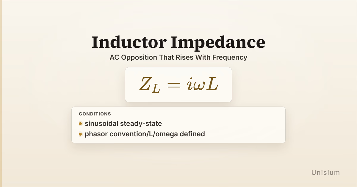
Inductor Impedance says that an inductor has impedance in sinusoidal steady-state phasor analysis. Its impedance is frequency dependent and imaginary, so a larger or larger gives larger opposition to AC current. Use it for inductor voltage-current phasors; do not treat an inductor like a resistor with fixed real impedance, and remember that its voltage phasor leads current by .
This guide completes the basic AC component lane in the Electromagnetism Principle Map, after Resistor Impedance and Capacitor Impedance. The surrounding decisions are choosing the phasor convention, identifying the selected element as an inductor, pairing that inductor’s voltage phasor with its current phasor, and keeping angular frequency defined. Those are setup choices around the principle, not new principle keys.
On this page: The Principle | Conditions | Misconceptions | Elaborative Encoding | Retrieval Practice | Worked Example | Solve a Problem | Related Principles | FAQ | Related Guides | How This Fits
The Principle
Statement
Inductor Impedance says that, in sinusoidal steady-state phasor analysis, an inductor’s impedance is . The inductor’s opposition to AC current increases as angular frequency or inductance increases. In the canonical convention used here, the factor makes the impedance positive imaginary.
Mathematical Form
Where:
- is the inductor impedance, in ohms
- is the imaginary unit
- is the angular frequency, in radians per second
- is the inductance, in henries
With the passive sign convention, the inductor voltage and current phasors are related by:
The impedance relation is the principle. The voltage-current equation is where that impedance is usually used in a phasor circuit calculation.
What positive imaginary impedance means
The factor rotates the current phasor by when you multiply by impedance to get voltage. With the convention used here, an inductor’s voltage phasor leads its current phasor by . If a course uses the opposite time-dependence convention for phasors, the sign attached to the imaginary unit may be stated differently; use the convention declared in the problem or course.
Conditions of Applicability
Condition: sinusoidal steady-state; phasor convention/L/omega defined
Practical modeling notes
- Sinusoidal steady-state means transients have died away and the circuit is being analyzed at one angular frequency.
- Phasor convention means the problem has chosen how sinusoidal time functions map to complex amplitudes.
- must be the inductance of the selected inductor or already reduced equivalent inductor.
- must be angular frequency, not ordinary frequency ; if a problem gives , convert using before applying the impedance relation.
When it does not apply directly
- Switching transient: an inductor immediately after a switch changes state is not yet a sinusoidal steady-state phasor problem.
- DC steady state: as approaches zero, the ideal inductor impedance approaches zero, so DC behavior should be handled with the appropriate circuit model.
- Non-ideal inductor: winding resistance, core losses, parasitic capacitance, or saturation require a fuller impedance model.
- Wrong element: a resistor or capacitor has its own impedance relation; do not reuse for another component.
Want the complete framework behind this guide? Read Masterful Learning.
Common Misconceptions
Misconception 1: An inductor has one fixed opposition like a resistor
The truth: Inductor impedance depends on and .
Why this matters: Higher-frequency signals see more opposition from an ideal inductor in the phasor model.
Misconception 2: Larger inductance lowers impedance
The truth: is in the numerator, so larger inductance gives larger impedance magnitude at the same angular frequency.
Why this matters: Larger inductors resist rapid AC current changes more strongly in ideal sinusoidal steady state.
Misconception 3: The imaginary unit is decoration
The truth: The carries the phase relation between inductor voltage and current.
Why this matters: Dropping can give a plausible magnitude while losing the phasor direction that AC circuit analysis needs.
Elaborative Encoding
Use these questions to build understanding before memorizing the formula. See Elaborative Encoding for the broader method.
Within the Principle
- Why does increasing make the magnitude of larger?
- What does the factor say about the phasor relation between inductor voltage and current?
For the Principle
- What wording in a problem tells you the circuit is being treated in sinusoidal steady state?
- Before writing , how would you check that belongs to the inductor whose phasor voltage and current you are relating?
Between Principles
- How does Inductor Voltage Relation prepare the voltage-current relation that inductor impedance uses in phasor form?
Generate an Example
- Describe one AC circuit situation where inductor impedance should be used and one nearby situation where a DC or transient model would be more appropriate.
Retrieval Practice
Answer from memory, then reveal the result and check it. See Retrieval Practice for the full study method.
State the principle in words: _____In sinusoidal steady-state phasor analysis, an inductor has frequency-dependent complex impedance equal to i omega L.
Write the canonical equation: _____
State the canonical condition: _____sinusoidal steady-state; phasor convention/L/omega defined
Worked Example
Use this worked example to practice Self-Explanation.
Problem
An AC circuit is in sinusoidal steady state using the phasor convention for this guide. An inductor has inductance and is driven at angular frequency . The current phasor through the inductor is . Find the inductor impedance and the inductor voltage phasor using the passive sign convention.
Step 1: Verbal Decoding
Target:
Given:
Constraints: sinusoidal steady-state; phasor convention chosen; inductor voltage and current use the passive sign convention
Step 2: Visual Decoding
Draw one inductor, mark the current reference through it, and mark the voltage polarity so the current enters the positive terminal. Sketch the current phasor on the real axis and place the inductor voltage phasor ahead of it under this convention. (The key visual fact is that inductor impedance rotates the voltage phasor relative to current.)
Step 3: Physics Modeling
Step 4: Mathematical Procedures
Step 5: Reflection
- Dimensional analysis: Radians are dimensionless, and henry times inverse seconds has units of ohms.
- Interpretation: The voltage phasor leads the current phasor by in this convention.
- Magnitude: An inductor at gives tens of ohms of reactance, so a current giving about one volt is plausible.
Before moving on: self-explain the model
Try explaining why Step 3 includes both the inductor impedance relation and the phasor voltage-current relation, but no resistor or capacitor impedance.
Physics model with explanation
Principle: We use Inductor Impedance because the problem asks for the phasor-domain model of one inductor.
Conditions: The circuit is in sinusoidal steady state, the phasor convention is given, and both and are defined, so the canonical condition is satisfied.
Relevance: The target is directly determined by and , and that impedance then links the inductor current phasor to the inductor voltage phasor.
Description: The inductor is one selected element. Under the passive sign convention and this phasor convention, multiplying its current phasor by gives a voltage phasor rotated by .
Goal: Compute the inductor impedance, then use it as the multiplier in the element’s phasor voltage-current relation.
Solve a Problem
Apply what you have learned with Problem Solving.
Problem
In a sinusoidal steady-state phasor circuit using the same convention as this guide, an inductor has and is driven at . The inductor voltage phasor is . Find and the current phasor through the inductor.
Hint: Write in polar form before dividing the voltage phasor by it.
Show Solution
Step 1: Verbal Decoding
Target:
Given:
Constraints: sinusoidal steady-state; phasor convention chosen; passive sign convention for the inductor
Step 2: Visual Decoding
Draw one inductor with the chosen voltage polarity and current reference. Sketch the voltage phasor at and put the current phasor behind it under this convention. (The key visual fact is that inductor voltage leads inductor current.)
Step 3: Physics Modeling
Step 4: Mathematical Procedures
Step 5: Reflection
- Dimensional analysis: Volts divided by ohms gives amperes, so the current unit is correct.
- Verification: Multiplying by returns .
- Interpretation: The current phasor lags the voltage phasor by , as expected for an inductor in this convention.
Related Principles
See Electromagnetism: The Principle Map for where inductor impedance sits in the AC device-and-network lane.
| Principle | Relationship to Inductor Impedance |
|---|---|
| Resistor Impedance | Contrasts with inductor impedance because resistor impedance is real and frequency independent. |
| Capacitor Impedance | Gives the complementary reactive relation whose magnitude decreases as angular frequency increases. |
| Inductor Voltage Relation | Supplies the time-domain relation that becomes the phasor-domain inductor impedance model. |
See Principle Structures for a broader way to organize DC relations, transient relations, and phasor-domain device models.
FAQ
What is inductor impedance?
Inductor impedance is . In sinusoidal steady-state phasor analysis, it is the complex impedance that relates an inductor’s voltage phasor to its current phasor.
When does i omega L apply?
It applies under the canonical condition: sinusoidal steady-state; phasor convention/L/omega defined. The problem must be using phasors, and both inductance and angular frequency must be known.
Why does inductor impedance increase at higher frequency?
The angular frequency is in the numerator of . As frequency increases, the inductor needs more voltage amplitude to support the same current amplitude in the ideal phasor model.
Does inductor current lead or lag voltage?
With the convention used by here, inductor current lags inductor voltage by . Always check the phasor convention because sign language can change across courses.
How is inductor impedance different from capacitor impedance?
Capacitor Impedance is , so its magnitude decreases as angular frequency increases. Inductor impedance is , so its magnitude increases as angular frequency increases.
Related Guides
- Electromagnetism Principle Map - Place inductor impedance in the AC circuits lane.
- Capacitor Impedance - Compare the complementary reactive element relation.
- Inductor Voltage Relation - Review the changing-current relation behind the inductor phasor model.
- Problem Solving - Practice turning circuit wording into the right model.
How This Fits in Unisium
Unisium treats Inductor Impedance as a principle because the equation is short but the representation boundary matters: it belongs to sinusoidal steady-state phasor analysis, and it applies to the selected inductor or equivalent inductor. The useful learning path is to encode why the impedance is proportional and imaginary, retrieve with its condition, self-explain voltage-current phasor examples, and solve new AC circuit problems after comparing resistor and capacitor impedance.
Ready to study physics principles this way? Check access and join the Unisium waitlist or explore the full framework in Masterful Learning.

Masterful Learning
The book behind these guides: a study system for physics, math, & programming built on retrieval, connection, explanation, and problem solving.
Ready to apply this strategy?
Unisium turns these evidence-based techniques into guided study sessions for math and physics. Places are limited during early access. Check current availability to start a trial; joining the mailing list is optional.
See plans and availability Read More GuidesAlready have access? Sign in