Inductance-Flux Relation: The Flux Linkage Model of a Coil
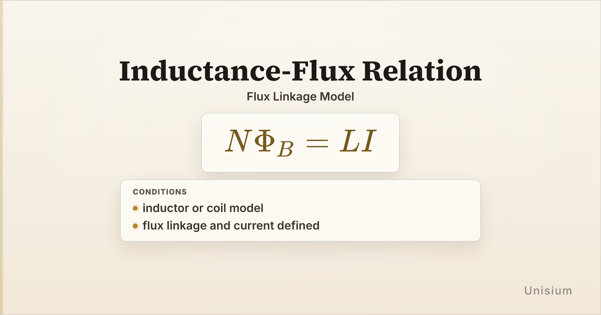
Inductance-Flux Relation says the magnetic flux linkage of a coil is proportional to its current: . It applies for an inductor or coil model when flux linkage and current are defined. Use it to connect current to linked magnetic flux, and do not confuse the flux through one turn with the total linkage .
This guide sits in the magnetic devices-and-networks lane of the Electromagnetism Principle Map, after magnetic flux ideas such as Magnetic Flux In A Uniform Field. The surrounding decisions are identifying an inductor or coil model, deciding what flux is linked by each turn, fixing the sign convention if direction matters, and judging whether a simple inductance model is adequate. Those choices support the relation; they are not separate principle keys.
On this page: The Principle | Conditions | Misconceptions | Elaborative Encoding | Retrieval Practice | Worked Example | Solve a Problem | Related Principles | FAQ | Related Guides | How This Fits
The Principle
Statement
Inductance-Flux Relation states that the total magnetic flux linkage of an inductor or coil is proportional to the current through it. If each of turns links magnetic flux , the total linkage is , and the proportionality constant is the inductance .
Mathematical Form
Where:
- is the number of linked turns
- is the magnetic flux through one turn, in webers
- is the inductance, in henries
- is the current through the inductor or coil, in amperes
- is the total flux linkage, in weber-turns
The diagram keeps the inductor recognizable: current follows the wound wire, straight flux lines thread the turns, a single linked turn is highlighted for , and the exiting bundle is labeled because the same per-turn flux is counted across linked turns.
Useful rearrangements
When the relation is valid, you can solve for any one of the linked quantities:
These are not new principles. They are algebraic rearrangements of the same flux-linkage model.
Conditions of Applicability
Condition: inductor or coil model; flux linkage and current defined
Practical modeling notes
- Inductor or coil model means the setup is being represented by one inductance , rather than by a detailed field calculation everywhere in space.
- Flux linkage defined means you know which turns link the magnetic flux being counted.
- Current defined means the current through the inductor or coil is the current used in the model.
- In many introductory problems, is treated as constant. If the core material saturates or the geometry changes, the model may need a more detailed inductance description.
- If sign matters, the chosen flux orientation and current direction must be consistent before interpreting positive or negative values.
When it does not apply directly
- No coil or lumped inductor model: a general magnetic-field situation may need a flux integral or field-source relation instead.
- Unclear linked turns: if only part of the coil links the flux, must match the turns that link that flux.
- Strongly nonlinear magnetic material: a single constant may not describe the current-flux relation over the whole range.
Want the complete framework behind this guide? Read Masterful Learning.
Common Misconceptions
Misconception 1: The equation uses flux through one turn only
The truth: The left side is , the total flux linkage. If is the flux through one linked turn, the turn count multiplies it.
Why this matters: Dropping gives the wrong current, flux, or inductance for a multi-turn coil.
Misconception 2: Inductance is the same thing as magnetic flux
The truth: Inductance is the proportionality between current and flux linkage. Flux linkage changes when the current changes, while describes the coil model.
Why this matters: Treating as flux hides the units and the role of current.
Misconception 3: The relation automatically handles every magnetic material
The truth: Many basic problems treat as constant, but real cores can make the current-flux relation nonlinear.
Elaborative Encoding
Use these questions to build understanding before memorizing the formula. See Elaborative Encoding for the broader method.
Within the Principle
- Why does the equation use instead of only ?
- What units must inductance have so that has units of flux linkage?
For the Principle
- What words in a problem tell you that a lumped inductor or coil model is intended?
- Before using the relation, how would you check whether refers to the turns linked by the stated flux?
Between Principles
- How does this relation build on Magnetic Flux In A Uniform Field without being a flux-through-surface formula itself?
Generate an Example
- Describe a coil where the current doubles while and stay fixed. What happens to the flux through each linked turn?
Retrieval Practice
Answer from memory, then reveal the result and check it. See Retrieval Practice for the full study method.
State the principle in words: _____For an inductor or coil model, total magnetic flux linkage equals inductance times current.
Write the canonical equation: _____
State the canonical condition: _____inductor or coil model; flux linkage and current defined
Worked Example
Use this worked example to practice Self-Explanation.
Problem
A coil has linked turns and inductance . When the current is , find the magnetic flux through each linked turn.
Step 1: Verbal Decoding
Target:
Given: , ,
Constraints: inductor or coil model; all stated turns link the same flux; flux linkage and current are defined
Step 2: Visual Decoding
Draw a coil, mark linked turns, and show the same flux threading each turn. Label current and flux per turn . (The key visual fact is that total linkage is , not only .)
Step 3: Physics Modeling
Step 4: Mathematical Procedures
Step 5: Reflection
- Dimensional analysis: A henry times an ampere is a weber, and dividing by a turn count leaves webers per linked turn.
- Interpretation: The answer is the flux through one turn; the total linkage is 200 times larger.
- Parameter dependence: If the current doubled while and stayed fixed, would double.
Before moving on: self-explain the model
Try explaining why Step 3 uses flux linkage, why the turn count is on the flux side, and why the answer is smaller than for a multi-turn coil.
Physics model with explanation
Principle: We use Inductance-Flux Relation because the problem gives an inductor or coil model, current, inductance, and linked turns.
Conditions: The coil is modeled by one inductance, and the current and flux linkage are defined.
Relevance: The target is the flux through each linked turn, so the flux-linkage relation directly connects the given current and inductance to .
Description: The product gives total flux linkage. Dividing by converts linkage into flux per linked turn.
Goal: Rearrange the relation for and substitute the coil data.
Solve a Problem
Apply what you have learned with Problem Solving.
Problem
An inductor has linked turns and inductance . The magnetic flux through each linked turn is . Find the current in the inductor.
Hint: First compute the total flux linkage .
Show Solution
Step 1: Verbal Decoding
Target:
Given: , ,
Constraints: inductor or coil model; all stated turns link the same flux; flux linkage and current are defined
Step 2: Visual Decoding
Draw a coil with many linked turns and mark one flux value through each turn. Label the total linkage as . (The key visual fact is that the linked flux adds over turns before solving for current.)
Step 3: Physics Modeling
Step 4: Mathematical Procedures
Step 5: Reflection
- Dimensional analysis: Webers divided by henries gives amperes because one henry is one weber per ampere.
- Verification: Substituting gives , matching .
- Interpretation: The current is set by total flux linkage, not by one-turn flux alone.
Related Principles
See Electromagnetism: The Principle Map for where inductance sits in the magnetic devices-and-networks lane.
| Principle | Relationship to Inductance-Flux Relation |
|---|---|
| Magnetic Flux In A Uniform Field | Defines how magnetic flux can be computed through a surface before it is counted as linkage. |
| Inductor Voltage Relation | Later relates inductor voltage to changing current once a sign convention is fixed. |
| Inductor Energy | Later uses inductance and current to model magnetic-field energy stored in an inductor. |
See Principle Structures for a broader view of how definitions prepare later device and circuit relations.
FAQ
What is the inductance-flux relation?
The relation is . It says total magnetic flux linkage equals inductance times current for an inductor or coil model.
What does flux linkage mean?
Flux linkage is the magnetic flux linked by the turns of a coil. If each of turns links flux , the total linkage is .
When does the inductance-flux relation apply?
It applies under the canonical condition: inductor or coil model; flux linkage and current defined. The setup must identify the coil or inductor model and the flux being counted.
Is inductance the same as flux?
No. Inductance is the proportionality between current and flux linkage. Flux linkage has units of webers or weber-turns, while inductance has units of henries.
Why is the number of turns in the formula?
The turn count converts flux through one linked turn into total flux linkage. More linked turns mean more total linkage for the same one-turn flux.
Related Guides
- Electromagnetism: The Principle Map - Place inductance in the broader EM structure.
- Magnetic Flux In A Uniform Field - Review how flux through a surface is represented.
- Magnetic Field In A Long Solenoid - Compare a coil-source magnetic-field model with the lumped inductance model.
- Problem Solving - Practice translating givens, assumptions, and diagrams into equations.
How This Fits in Unisium
Unisium treats Inductance-Flux Relation as a principle because the equation is short but the representation is easy to compress incorrectly. The useful learning path is to encode the difference between one-turn flux and flux linkage, retrieve with its exact condition, self-explain the coil model, and solve new problems where the target changes.
Ready to master Inductance-Flux Relation? Check access and join the Unisium waitlist or explore the full framework in Masterful Learning.
Masterful Learning
The book behind these guides: a study system for physics, math, & programming built on retrieval, connection, explanation, and problem solving.
Ready to apply this strategy?
Unisium turns these evidence-based techniques into guided study sessions for math and physics. Places are limited during early access. Check current availability to start a trial; joining the mailing list is optional.
See plans and availability Read More GuidesAlready have access? Sign in